
Mold Consumables
Core Pins
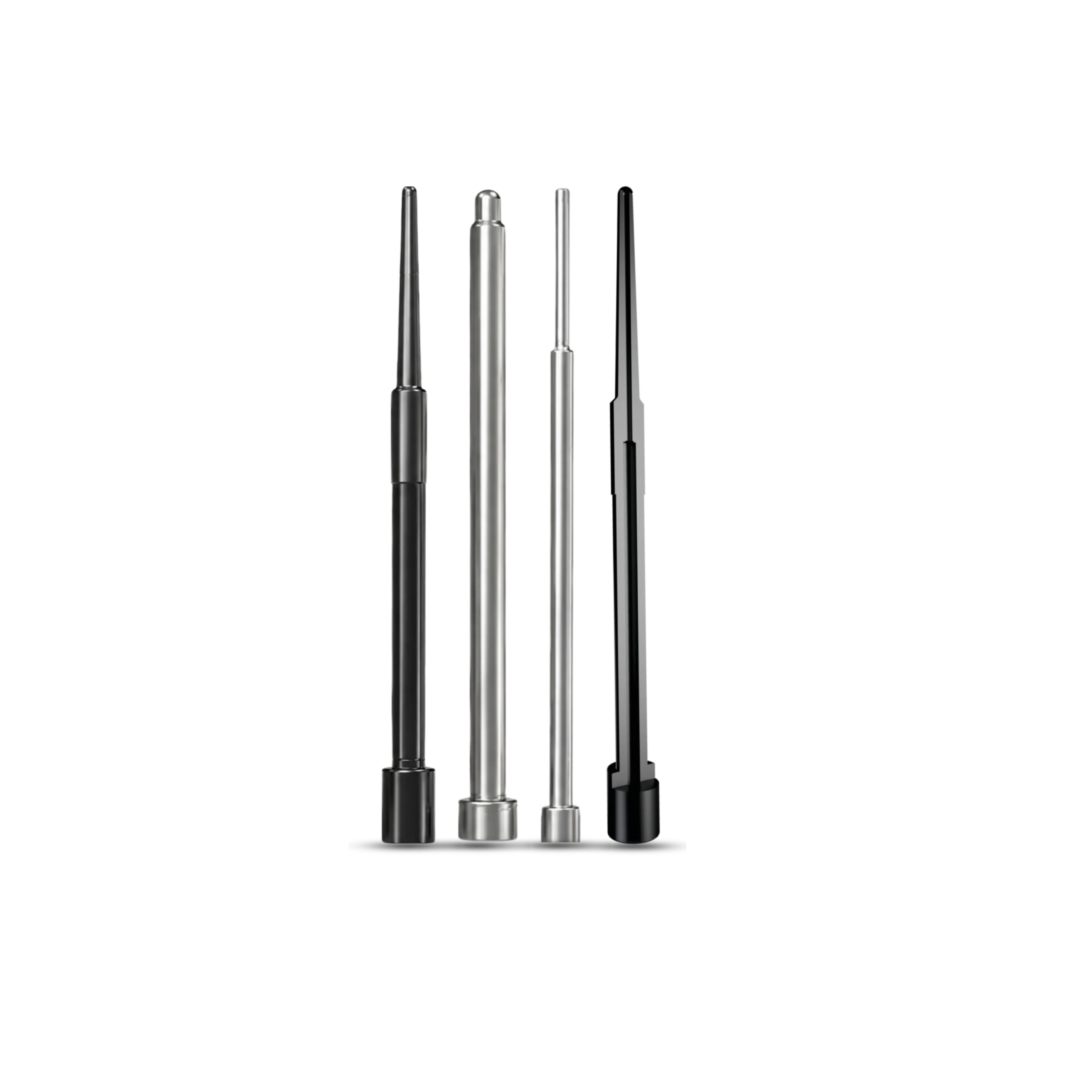
Precisely machined and ground pins for forming holes in die castings. Made to your drawing.
Solid core pins
Solid throughout, with no internal cooling bore.
Jet-cooled core pins
An internal bore receives the jet cooler tube for cooling within the pin.
Internal cooling
Jet-cooled pins pair with jet coolers to direct water and air into the bore. The drawing and available wall thickness determine the cooling arrangement.
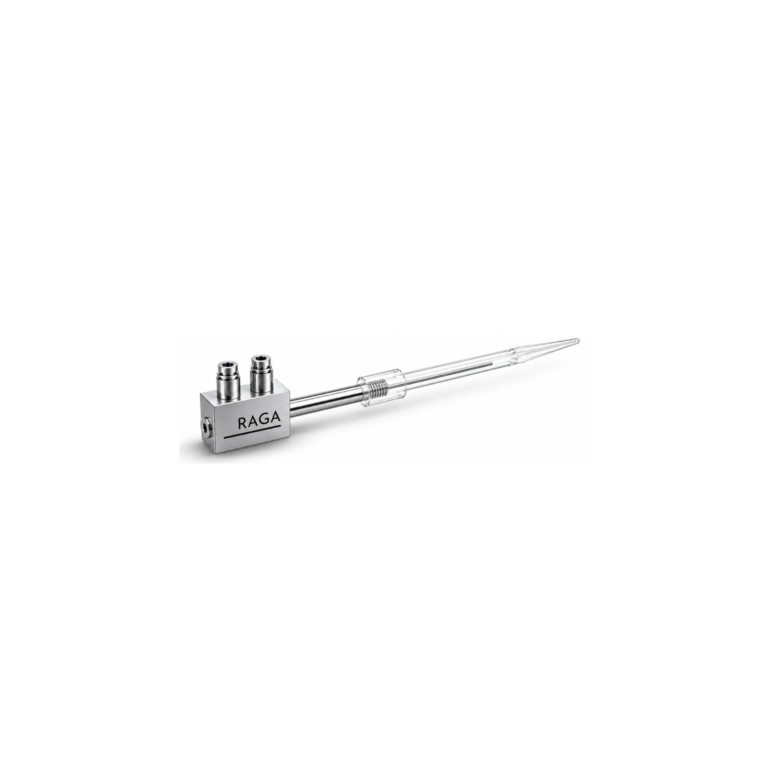
Jet cooler fitted inside a jet-cooled core pin · section through the mold
Materials, treatment and inspection
| Area | Available details |
|---|---|
| Material | H13 / DIN 1.2344; specify the required material designation on the drawing. |
| Heat treatment | Vacuum hardening and three tempering cycles. |
| Surface treatment | Gas nitriding; optional PVD coating. |
| Dimensional inspection | Pin dimensions checked against the drawing. |
| Cooling bore | Diameter and depth selected together for the pin geometry and required wall thickness. |
Cooling bore specifications
| Parameter | Catalogue capability |
|---|---|
| Cooling bore diameter | 2–6 mm |
| Maximum bore length | Up to 600 mm |
| Length-to-diameter ratio | Up to 125 |
| Minimum pin-tip diameter | 4 mm, subject to required wall thickness |
| Bore centerline deviation | Maximum 0.1 mm per 100 mm drilling depth |
| Bore-straightness inspection | 100% inspection for jet-cooled pins |
Maximum length depends on bore diameter and pin geometry; the limits are not all simultaneously available.
Drawing requirements
Send the drawing and revision with any material, surface treatment or cooling requirements.
- Part drawing and revision
- Material and treatment requirements
- Solid or jet-cooled design
- Quantity and application details